This article is about an ambulance siren made from transistors.

You can see the circuit working in this video:
This is the power bank that I used (6 V AA battery holder):

Figure 2: 6 V battery holder.
Step 1: Design the Circuits
I have drawn the circuit in PSpice simulation software:
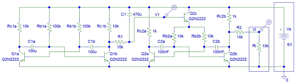
You can also implement this circuit if you do not have enough NPN transistors:

Figure 4: Oscillator Circuit 2.
C1 is the frequency sweep control capacitor. You can select C1 of 100 uF. I used C1 of 470 uF.
The power amplifier is not linear because it is not used for audio (it would NOT work for audio signals) but square wave only.

Figure 5: Power Amplifier.
Step 2: Simulations
Simulations show that the two oscillator circuits are similar:

Figure 6: Oscillator Circuit 1 Simulations.

You can see the maximum current output of the power amplifier:
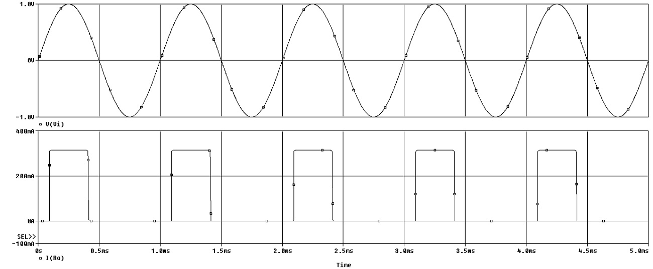
Figure 8: Power Amplifier Simulations.
Step 3: Make the Circuits
The three LEDs are connected to the power supply in series with a 100-ohm resistor.

Figure 9: Make the Oscillator.
The two black 100 uF electrolytic capacitors are bipolar.
I used high power resistors just for the image:

Step 4: Testing
Testing showed that the circuit is working:


Step 5: Assembly

Figure 14: Assembly.
Conclusion
Let's just hope that you (the reader of this article) will not need to hear this sound.
No comments:
Post a Comment